Projects
These are mostly from high school, a few of the later electronics projects were done in my first year of college. After that, most of my personal projects were put on the backburner so I could focus on research work. This page is crudely ripped from my old website, so I apologize for formatting errors.
Project Overview
Here is a basic overview of my projects (Up to December 2019)
Full, in-depth documentation of my largest project, Aeronef, can be found in the YouTube playlist below.
Aeronef Documentation
RC Navigation & Mapping
Navigation
The navigation is admittedly rather simple, but it can explore a pathway/building completely independently, without crashing. It also manages speed depending on the situation (i.e. slower when turning or when there is a wall ahead).
Map Generation
After nearly a year of working on the project, I decided that for better software testing, I would need more virtual maps to demo in— but there were none online. So, I decided to make a rather basic script to randomly generate a map for the car to test in.
Mapping
This is the portion I have been most passionate about, as evidenced by the file’s line count (2280 lines of code). For the first couple of months, I used the lidar to take in data and find a “line-of-best-fit” between data-points, thus creating various walls. However, it was inefficient, and when a driving algorithm is inefficient, crashes are rather frequent. Eventually, I devised a new system, instead of making lines, I would treat the individual data-points as nodes. Once the data was taken in, the nodes were strung together, and unnecessary nodes were removed. This system is able to drive around a track, taking in well over eight thousand data-points, and create an accurate map of a mere forty nodes.
3D Function Visualizer
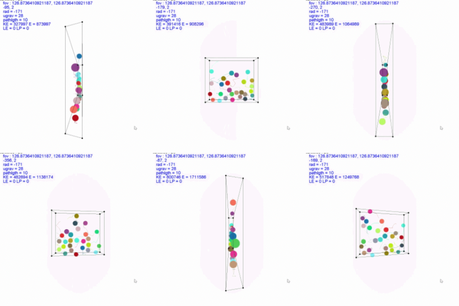
This project originated as a 3D particle simulator (which can be seen below), but soon progressed into an experiment with 3D functions. I realized that if I created a 2D-float-array, I could use the value of each index as the z-position, and the two array indexes as the x and y. Hence, by inputting a simple z=f(x,y) function, it could create a 3D rendering of it by drawing lines to adjacent indexes.
The first problem I had with this was how to handle 3D-rotations of perspective, and since I was unable to find much helpful information on how to use quaternions, I struggled with making it work. However, I eventually just settled on the admittedly inefficient method of rotationally-translating each point around the origin every render.
Eventually, while doing schoolwork, I realized I could alter my original method to graph polar functions. By replacing the float-array with a vector-array, I could instead have the array indexes represent the x-y orientation from the origin and store the x-y positions in the vector. This worked surprisingly well, and after I made an algorithm to panel the graphs and render them in order of distance from the observer, I started to realize the potential this program had.
Finally, I upgraded it to render parametric equations by using the x-index as a fourth variable, time. First, I made basic parametric functions with {x=f(t), y=g(t), z=h(t)}, but later added Euler approximation compatibility, using the y-index as a different initial position, with the input parameter being the derivative functions of each position variable.
3D Particle Simulator

I had made several particle simulators prior to this one, but since they were all 2D, I was always annoyed with my inability to model electromagnetism. Since electromagnetism is an inherently 3D force, as demonstrated by the right-hand rule, I knew I had to make a 3D-environment. So, I made this using Java’s Applet graphics library.
It can model gravity, electromagnetism, pressure, and collisions between particles and trace their paths.
Engineering / Design Projects
Electric Shopping Cart (2019)
I made this a couple of months ago, and at the time, it was pretty much my only large-scale project that involved much hardware. The original idea was born from a desire to take my team’s work in Autonomous Vehicles to the next level, but that never really worked out with my teacher. So it became a passion project until I finished it after a couple of weeks. I found the cart abandoned in the woods near my house, and using some electronics from my basement, managed to power it with electric motors. Eventually, I managed to make it controllable via a python script on my laptop.
Custom Coilgun (2020)

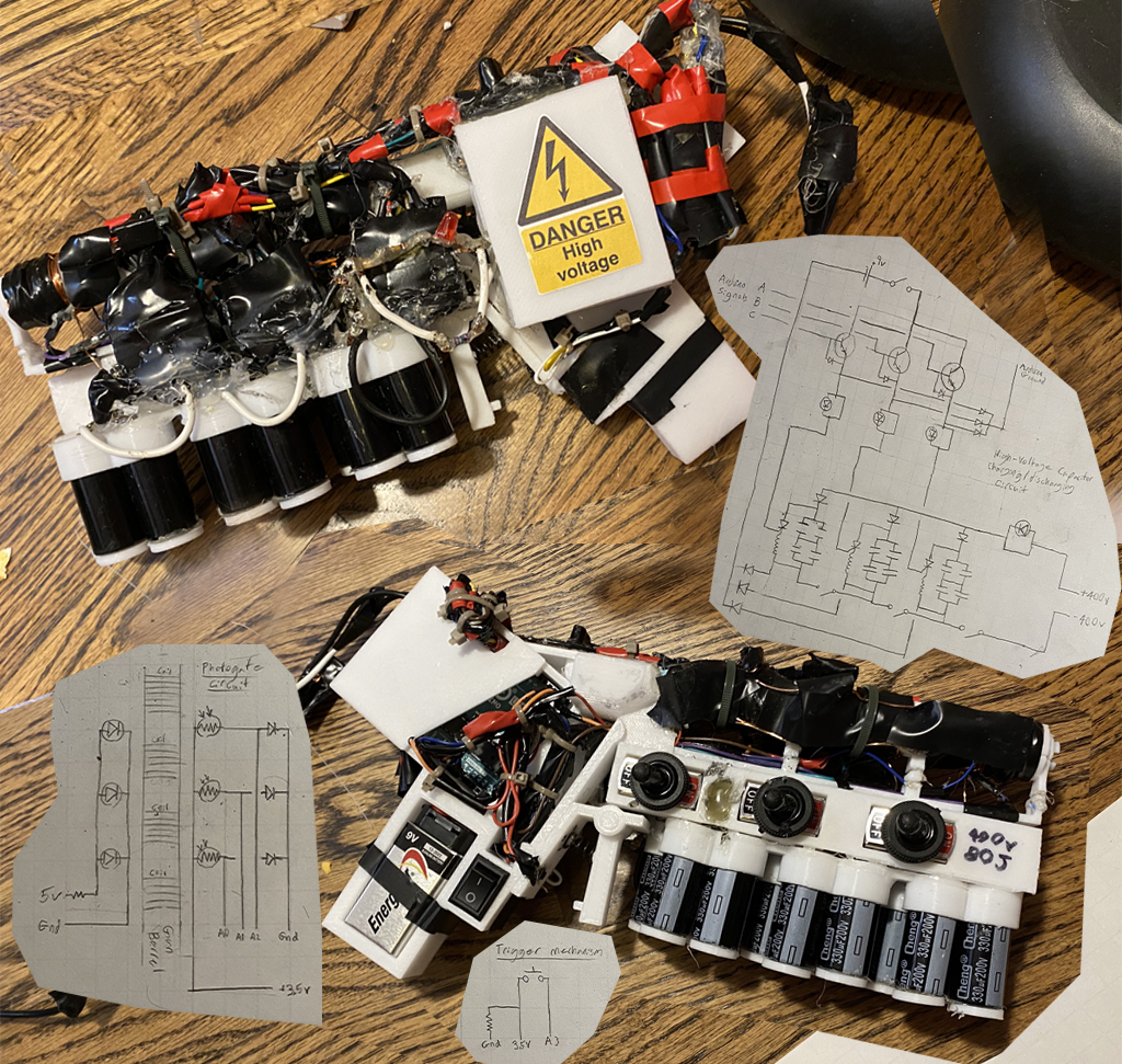
I have currently spent over 110 hours working on this first Coilgun. I built it entirely from scratch using onshape to design the plastic frame, and buying misc parts (i.e. capacitors, copper wire, thyristors, switches, etc) online. It's been a fun way to spend my time while in quarantine, but is not working as well as I would like it to yet.
Coil Rifle (2020-2021)

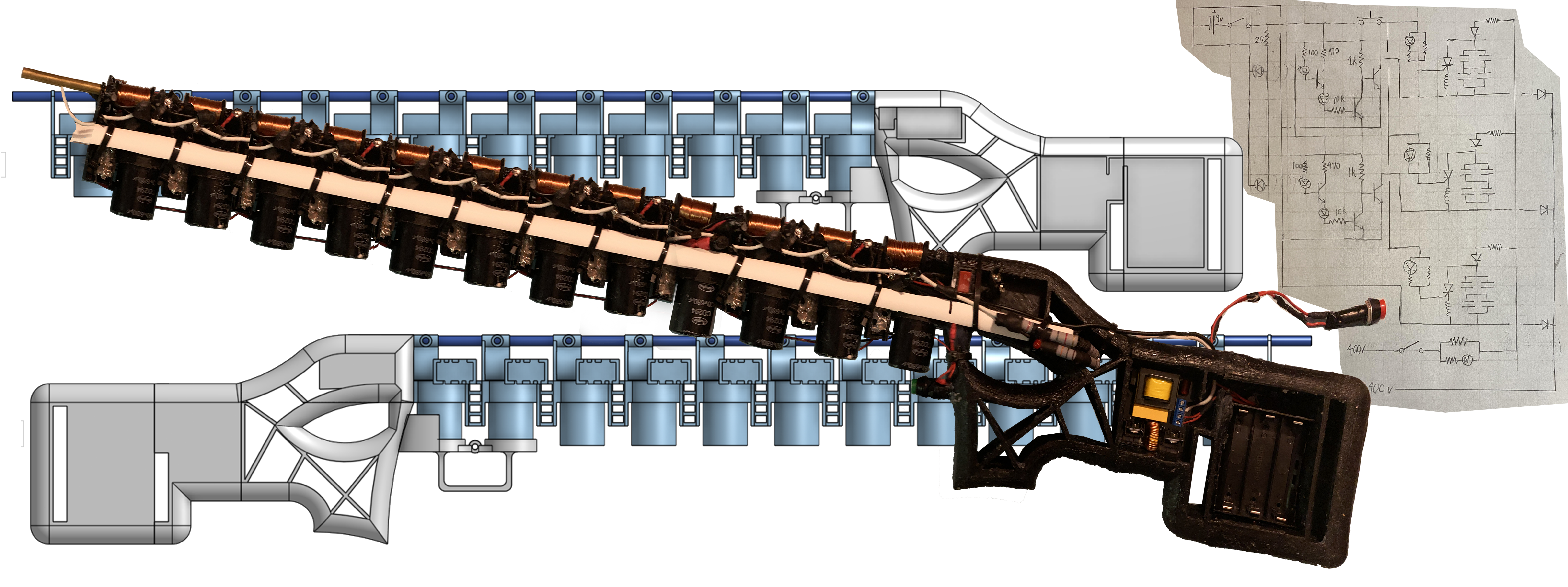
This is the current version my coilgun project. After I got more familiar with circuits, I found a way to make it work without an arduino, so I decided to start building a new, better coilgun. This version works with absolutely no software component, and is controlled entirely by my logic circuit.
Unfortunately, I had to start college before I was able to complete this project, and due to housing regulations, I was unable to bring it with me. However, I do hope to complete it eventually, and I am satisfied with its current operation and appearance.
Analog/RTL Autonomous Car (2021)
I started this project after taking a class on logic circuits second semester of college. The basic idea was to design and build a basic wall-following circuit for an RC car I had and some HC-SR04 sonar sensors. While working on my AV project in high school, I realized you can make the car run reasonably well through a course by just assigning the turn angle to the ratio of left-right wall distances, and control the speed with the forward distance. For this project, I implemented this algorithm with analog and RTL components. The distances were measured by controlling the sonar sensors with 555 timers to send the initial pulse, and counters to measure the time it takes to receive the signal back. I then used basic mathematical ICs to find the ratio. Finally, since the motors were controlled via PWM, I built an analog-PWM converter.
Whistle Detector (2021)
Designed, simulated, and built an analog circuit to detect my whistle at a frequency of 1500 Hz. Used a non-degenerated common-emitter amplifier to detect the audio, then reduced the output resistance with a unity gain amplifier. The output was then fed into a Sallen-Key filter to single out the whistle frequency. The amplitude is extracted with a peak detector and displayed by a LED.